
When it comes to handling horizontal ingots, lifting equipment options are numerous and varied. With so many options, it can be difficult to decide what would best suit your application. This post will cover some of the solutions Bradley Lifting offers, as well as provide some guidance on choosing a lifter that will integrate well into your process.
Mechanical Units
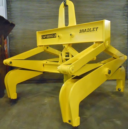
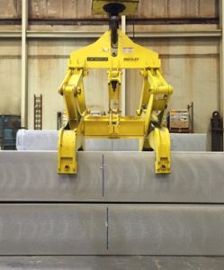
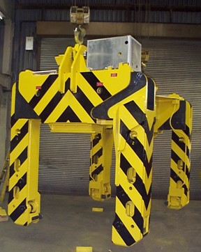
Tongs
For ingots with a limited width range, a mechanical tong is an excellent option. This unit type typically features four legs, each with a replaceable grip point or grip pad, to attach to the load. While the standard grip option is a point, grip pads can sometimes be provided if the edge finish of the ingot is a concern.
Automatic latches are provided to alternately hold the legs open and allow them to close with vertical hoist motion, which allows the unit to be operated without assistance from floor personnel.
These units can be configured for almost any hoist configuration – Single, double, or duplex hooks, as well as clevis connections and many others.
The downside to a mechanical tong is the limit in the range of widths a single tong can handle. If you’re looking to handle ingots with a large variation in width (typically, anything more than a 60% difference between the smallest and largest width), a motorized unit is likely the better option.
Motorized Units
Motorized Screw-Driven Grabs
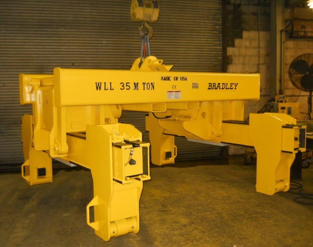
Handling ingots with a large variation in width, or in an automated facility, calls for a motorized lifter. The most common motorized unit type we offer is a motorized, screw-driven grab. This unit typically consists of a fixed upper beam assembly with at least two motorized grab arms. For exceedingly long ingots, the grab can be designed with multiple arms.
The grab arms are suspended by pivoted links to compensate for misalignment of the ingot sides and to assure that all four jaws securely clamp the load. Each grab is independently driven to ensure adequate grip is employed.
As with the Automatic Tongs, the legs of these units typically feature replaceable tool steel grip points, though grip pads can sometimes be used if the surface finish of the ingot sides is a concern. Each jaw features a cam grip mechanism to provide final grip on the sides of the ingot proportional to the load being lifted. The initial grip is provided by the electromechanical drive, with the final grip being applied by the cam mechanism.
The legs are driven “in and out” by a brake motor directly coupled to a worm gear reducer, and chain drive to final Acme screw with bronze nuts. These units can be designed for almost any power source, with 480/3/60 being the most common.
Like the Automatic Tong, these units can be designed for most hoist setups.
Telescoping Ingot Lifter – Lifting Feet
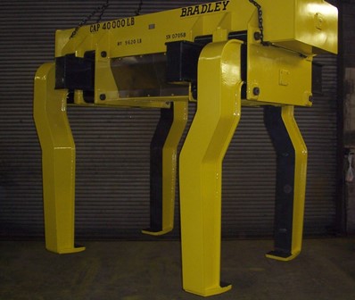
If no damage to the sides of the ingot is allowable, such as with ingots after saw cutting, the best option will be a Motorized Telescoping Ingot Lifter. This unit handles ingots from below, so grip points or pads aren’t required to safely handle the load. The lifting feet can be covered with replaceable liners, to offer additional surface protection.
Besides the lifting operation, the other major difference these units have over Motorized Screw Driven Grabs have is the drive configuration itself – the legs are driven in and out by a gearmotor with brake, torque limiter, worm gear reducer, and chain drive, but instead of an Acme screw and bronze nuts, the final drive is a rack and pinion. Dual sliding members are used for better support of the telescoping legs with replaceable brass wear plates in the frame.
Telescoping Screw Driven Ingot Grab
The final lifter type we’ll discuss in this post is a specialized unit – a telescoping screw-driven ingot grab. This unit type is best suited in applications with limited space – such as ingot storage facilities.
Unlike the Motorized Screw Driven Grabs, the entire leg of this unit is driven, which allows the unit to fit between rows of stacked ingots more easily.
These units typically consist of two sets of motorized legs that are driven “in and out” along a main frame. The motors exert an initial grip on the load with a final mechanical grip applied by cam linkages in each leg.
Each pair of legs are individually driven by an electric motor with brake, jaw-type coupling, cone drive worm gear reducer, chain drive with impact coupling, and final Acme screw and bronze nuts.
Hopefully, this brief overview of the different types of horizontal ingot handling equipment gave you a better understanding of your options, and some idea when to use a specific piece of equipment. Of course, Bradley Applications Engineers are always available to assist you with your projects. If you have any questions Click Here to contact us, and we’ll be glad to answer any of your questions.